Arctos Robot Arm Documentation
Build your own 6-axis robotic arm. Open source, 3D printed, and community driven.
Start with the Quick Start Guide to get an overview of the build process, estimated time, and required skills.
Project Overview
The Arctos robot arm comes in two control system options, each designed for different needs and skill levels:
Control system without position feedback. Simpler to build and program, ideal for beginners learning robotics fundamentals.
Advanced control system with encoder feedback for precise positioning. More capable but requires additional configuration.
This documentation focuses on the Closed Loop system as it represents the latest improvements. Use the version selector in the header to switch between control systems.
At a Glance
Join the Community
Get help, share your build, and connect with other makers:
Quick Start Guide
Everything you need to know before starting your Arctos build.
Please read the entire Safety section before starting. This robot uses high currents that can cause burns or electrical shock if mishandled.
Build Overview
Build Steps
Order parts from the BOM, prepare your 3D printer, and gather required tools (Allen keys, soldering iron, pliers).
Print test_print.stl to verify your printer settings and hardware fitment before printing all 168 parts.
Print parts axis by axis (X→Y→Z→A→B→C). Gearboxes first, cover panels last. Expect 80-100 hours of print time.
Build the cycloidal (Y, Z axes) and planetary (A, B, C axes) gearboxes. Follow the 3D assembly manual carefully.
Configure MKS drivers, glue magnets to motor shafts, and prepare all wiring BEFORE mounting motors.
Assemble each axis following the interactive 3D manual. Install belts, endstops, and wiring.
Flash firmware, configure Arctos Studio, calibrate each axis, and run your first program!
Pre-Build Checklist
- 3D printer calibrated and working (0.4mm nozzle recommended)
- 4kg of PLA filament (2 colors for two-tone look)
- Hardware kit ordered or parts sourced from BOM
- Allen keys (2.5, 3, 4, 6mm), pliers, tweezers ready
- Soldering iron and solder available
- Read the Safety section completely
- Joined Discord for community support
3D Printing Checklist
- Printed and tested test_print.stl for fitment
- All X axis parts printed
- All Y axis parts printed
- All Z axis parts printed
- All A axis parts printed
- All B axis parts printed
- All C axis parts printed
- Gripper parts printed
Assembly Checklist
- Y axis cycloidal gearbox assembled
- Z axis cycloidal gearbox assembled
- A, B, C planetary gearboxes assembled
- Magnets glued to all motor shafts
- X axis fully assembled
- Y axis fully assembled
- Z axis fully assembled
- A axis fully assembled
- B axis fully assembled
- C axis fully assembled
- Gripper assembled and mounted
Electronics & Software Checklist
- All drivers configured with correct IDs
- All wiring completed and checked
- Endstops installed and tested
- Firmware flashed successfully
- Software installed and configured
- All axes calibrated
- First successful movement test
- First program executed successfully
Required Skills
| Skill | Level Required | Notes |
|---|---|---|
| 3D Printing | Intermediate | Must be able to print with supports, adjust settings |
| Soldering | Basic | Wire tinning and basic connections |
| Electronics | Basic | Understanding of power, ground, signal wires |
| Mechanical Assembly | Intermediate | Patience with small parts and tight tolerances |
Head to the Bill of Materials to order your parts, or check the 3D Printing section to start printing!
⚠️ Safety First
Critical safety information you MUST read before building or operating the Arctos robot.
This robot can electrocute you. Make sure all wires are secured before turning on power. Never work on the robot while it’s powered.
Electrical Safety
- Always disconnect power before working on wiring or electronics
- Tin all wire tips and secure them firmly in terminals to prevent short circuits
- Check polarity carefully — reversed polarity will permanently damage MKS drivers
- Use appropriate wire gauges — thin wires can overheat and cause fires
- Inspect connections regularly — loose connections generate heat
Stepper motors running at high current can get extremely hot. Adjust current limits to prevent overheating. If a motor is too hot to touch, reduce the current immediately.
Mechanical Safety
- Robot joints can pinch and crush — keep fingers clear during operation
- Gearboxes have significant torque — they can cause injury if fingers get caught
- Use caution when removing supports — sharp tools can cause cuts
- 3D printer and soldering iron — standard hot tool safety applies
- Wear safety glasses when removing supports or working with small parts
Safe Operation
- Always start with slow movements when testing
- Keep the work area clear of obstacles
- Never leave the robot running unattended
- Install and test endstops before full operation
- Have an emergency stop plan (power switch accessible)
- Bolt the robot to a secure surface — the robot can tip over during operation if not properly secured
Common Mistakes to Avoid
Consequence: Permanently destroys the MKS driver board instantly.
Prevention: Triple-check polarity before connecting power. Red to +, Black to -. When in doubt, use a multimeter.
Consequence: Motors overheat, can cause burns, damage motors, or start fires.
Prevention: Start with lower current settings and increase gradually. If motor is too hot to touch, reduce current.
Consequence: Driver is permanently damaged.
Prevention: Check orientation markings on driver and socket. The potentiometer usually faces a specific direction.
Consequence: Can damage driver or cause unexpected motor movement.
Prevention: Always power off before adjusting the potentiometer on stepper drivers.
Building a robot can be frustrating. Parts may not fit, prints may fail, and things may not work the first time. Take breaks, ask for help on Discord, and remember: every successful build had setbacks along the way!
Specifications
Technical specifications and parameters for the Arctos robot arm.
Dimensions & Capabilities

Software Compatibility
- Arctos Studio — Native control software with GUI, calibration, and programming
- Nvidia Isaac Sim — Advanced simulation and AI training
- ROS1 & ROS2 — Robot Operating System integration
- GrblGru — Open-source control software
- Robot Overlord — Visualization and control
- Matlab — Advanced kinematics and control
- Unity — 3D simulation (in progress)
Axes Nomenclature
Each axis has a specific name, joint designation, link name, and CAN ID:
| Axis | Joint | Link | CAN ID |
|---|---|---|---|
| X (Base) | joint1 | Link_1_1 | 01 |
| Y (Shoulder) | joint2 | Link_2_1 | 02 |
| Z (Elbow) | joint3 | Link_3_1 | 03 |
| A (Wrist 1) | joint4 | Link_4_1 | 04 |
| B (Wrist 2) | joint5 | Link_5_1 | 07 |
| C (Wrist 3) | joint6 | Link_6_1 | 06 |
Work Envelope

Denavit-Hartenberg Parameters


Gear Ratios
| Axis | Gear Ratio | Gearbox Type |
|---|---|---|
| X | 1:13.5 | Belt reduction |
| Y | 1:150 | Cycloidal |
| Z | 1:150 | Cycloidal |
| A | 1:48 | Compound Planetary |
| B | 1:67.82 | Compound Planetary |
| C | 1:67.82 | Compound Planetary |
Bill of Materials
Complete list of parts needed to build your Arctos robot arm.
The complete BOM with quantities, links, and prices is available at arctosrobotics.com/bom or on Google Sheets.
Pre-Made Kits
The easiest way to get started is with a pre-made kit:
All 168 3D printed parts, ready to assemble. Save 80+ hours of printing time.
Complete hardware kit with all electronics, motors, and fasteners.
Hardware kit available on Amazon for faster shipping in some regions.
Version Comparison
| Feature | Open Loop | Closed Loop |
|---|---|---|
| Position Feedback | No | Yes (encoders) |
| Cost | Lower (~$300) | Higher (~$500) |
| Wiring Complexity | More wires | Fewer wires (CAN bus) |
| Programming | Simpler (GRBL) | More complex |
| Precision | Good | Excellent |
| Payload | 1kg | 1kg |
Self-Sourcing Parts
You can also source parts yourself to save money or customize:
- Threaded rods: Buy 1m M4 rod and cut to length. Drywall anchors (4mm diameter) work as cycloidal pins.
- Bearings: Can be salvaged from old 3D printers or bought in bulk.
- Motors: If using different motors, adapt the CAD files to fit.
- Fasteners: Local hardware stores often have better prices than online.
Check the community mods page and Discord #showcase channel for alternative parts and modifications others have made.
Kit Contents Overview
Visit arctosrobotics.com/robot-kits to see all available kit options and what’s included.
3D Printing Instructions
Print settings, part orientation, and tips for successful prints.
Before printing all 168 parts, print the test_print.stl to verify hardware fitment. If parts don’t fit, adjust your printer settings or modify bearing clearances in the Fusion 360 file.
A 200x200mm print bed is required. Some users have printed on 180x180mm beds, but some parts needed to be separated into multiple pieces.
Recommended Print Settings
| Setting | Value | Notes |
|---|---|---|
| Material | PLA | PETG also works but may need adjustments |
| Nozzle Temp | 215°C | Adjust for your filament brand |
| Layer Height | 0.2mm | Balance of speed and quality |
| Extrusion Width | 0.4mm | Standard 0.4mm nozzle |
| Infill | 35% | Good strength without excess weight |
| Wall Count | 4 | Important for structural parts |
| Top/Bottom Layers | 4 | Solid top and bottom surfaces |
| Supports | Required | Many parts need supports – check each one! |

Bambu Lab Print Settings

Pre-Oriented Print Plates
The CAD files include pre-oriented print plates with all parts positioned optimally. Print the plates in order from bottom to top for the most efficient workflow.

Printing Order
Print gearboxes first, cover panels last. This lets you start assembly while still printing cosmetic parts.
Part Organization
- Parts are organized by axis: X → Y → Z → A → B → C
- Search the STL folder for axis name (e.g., “X”) to find all parts for that axis
- Total: 168 parts (some are duplicates like gears)
Part Naming Convention
Example: Z R lower core (1)_1-Z R lower core-stl.stl
- Z = Axis name
- R = Right side (L = Left)
- lower = Position (vs “upper”)
- core = Part type
- (1) = Can be ignored (export artifact)
Two-Tone Printing
For a professional two-tone look:
- Search for “cover”, “panel”, “pulley” → print in accent color
- Search for “core” → print in main color
- Check the Fusion 360 file or Discord #showcase for inspiration
Supports & Orientation
Many parts require supports. Some prints take 6-7 hours — discovering missing supports after the print fails is frustrating. Double-check every part in your slicer before printing.
Support Removal Tips
- Use a small flat screwdriver to pry supports
- Pliers help grip and twist supports off
- Utility knife for cleanup
- Orca Slicer creates easy-to-remove supports with good interface layers
Tolerances & Fit
Many holes are designed for tight fits with bolts. If parts don’t fit:
- Check your printer’s dimensional accuracy
- Adjust bearing clearances in the Fusion 360 source file
- Use a deburring tool or drill to clean up holes
- Try printing at 99% scale if parts are consistently oversized
Required Tools
| Category | Items |
|---|---|
| Allen Keys | 2.5mm, 3mm, 4mm, 6mm |
| Hand Tools | Pliers, tweezers, utility knife, lighter |
| Electric Tools | Soldering iron (or Wago clips as alternative), drill (optional) |
| Screwdrivers | Phillips, flat head |
| Other | Superglue, deburring tool, small hammer |
Assembly Instructions
Step-by-step guides to assemble your Arctos robot arm.
Interactive Assembly Manual
The best way to follow assembly is with our interactive manual that shows each step in detail:
Interactive 3D web viewer with step-by-step instructions for the latest version.
Original PDF-style assembly manual for version 0.1.
Video Assembly Guide

This video is for v2.0. We are currently at v2.9.7. The main differences are in mounting the motors to A, B, C axes. Refer to the 3D assembly manual for the latest mounting instructions.
Assembly Timelapse

X Axis Assembly

More axis-specific assembly videos coming soon!
The following steps are not shown in the assembly manuals but are critical:
- Glue magnets on each stepper motor shaft
- Prepare and configure MKS driver wires BEFORE bolting motors
- Install on/off switch and LED indicator
Gearbox Assembly
Cycloidal Gearboxes (Y & Z Axes)
Cycloidal gearboxes provide high reduction ratios (1:24 per stage, 150:1 total) in a compact package. They’re ideal for 3D printing because they:
- Run quietly
- Have minimal backlash
- Don’t wear significantly over time
- Work well with FDM tolerances

Key Assembly Points:
- Three cycloidal disks rotate eccentrically at 120° to each other
- 25 stainless steel 4mm dowel pins on the outside
- 5 threaded rods on the inside contact bearings (618/6 for Y, 688 for Z)
- The last threaded rod should have resistance when inserting — this indicates correct assembly

Use a small 4mm dowel pin to lock the disks in alignment before installing them in the casing. Follow the camshaft part order and disk order shown in the manual.
Compound Planetary Gearboxes (A, B, C Axes)
Compound planetary gearboxes are lighter and achieve even higher reduction ratios than cycloidals. They’re used in the upper arm where weight matters most.
Trade-offs:
- Noisier during operation
- Require lubrication
- Experience more wear over time
Pay attention to the orientation of planetary gears during assembly — they must align as shown in the assembly manual images.
Additional Video Resources
Community members have created excellent build videos on their YouTube channels. Big thanks to these contributors:
If you get stuck, join our Discord server where the community can help troubleshoot assembly issues.
Wiring and Electronics
Complete wiring guides for both Open Loop and Closed Loop versions.
Reversing MKS driver polarity will permanently destroy the board. Triple-check all power connections before applying power. Tin wire tips and secure them firmly to prevent short circuits.
Components
- CANable adapter v2 — USB to CAN interface
- 4x MKS Servo 42D — Closed-loop drivers for smaller motors
- 2x MKS Servo 57D — Closed-loop drivers for larger motors
- 3x WSH231 — Dual hall effect sensors
- 6x KY-003 — Hall effect limit switches
Wiring Diagram

All components are daisy-chained from the CANable adapter to the C servo. Both ends of the chain require a 120Ω termination resistor.
Connect all wires to MKS drivers BEFORE bolting down the motors. Once mounted, there’s no space to add wires on A, B, and C axes.
Configuring MKS Drivers
Configure each MKS Servo driver with the correct CAN ID:
| Axis | CAN ID | Driver |
|---|---|---|
| X | 01 | MKS 57D |
| Y | 02 | MKS 57D |
| Z | 03 | MKS 42D |
| A | 04 | MKS 42D |
| B | 05 | MKS 42D |
| C | 06 | MKS 42D |
Use this magnet mounting jig (by DavidD) to center magnets on motor shafts.

Port Remapping
MKS57D (X and Y axes)
No remapping needed — they natively support two limit sensors (IN_1 and IN_2). However:
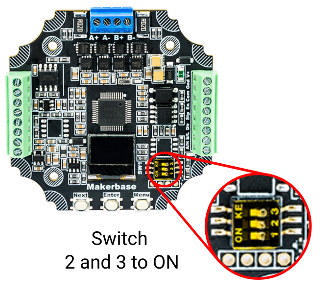
- Flip DIP switches 2 and 3 to “ON” to power the sensors
- Enable limits via MKS menu (“EndLimit”) or serial command 90
MKS42D (Z, A, B, C axes)
Requires pin remapping to use two limit switches:
Send via: Arctos Studio → Settings → MKS Settings → IO Control
Testing Endstops
- Put a magnet near each sensor — verify it lights up
- WITHOUT belt fitted, send HOME command or use MKS menu “GoHome”
- Motor should rotate slowly until sensor on IN1 triggers
- Send command to drive opposite direction, manually trigger other sensor — motor should stop
- When mounted, adjust sensor positions relative to magnets before fitting belt

Components
- Arduino Mega 2560
- 2x CNC Shield V3
- 6x TMC2209 stepper drivers
Wiring Diagram

Control Commands
The open loop version uses GRBL firmware and accepts G-code commands. Use RoboDK postprocessor for Arctos to generate code in this format:
- F800 — Feedrate (adjust as needed)
- G90 — Absolute coordinates (vs G91 relative)
Stream G-code to Arduino using Universal Gcode Sender or similar software.
Configuration Videos

Open Source Closed Loop Drivers (In Development)
We are developing open source closed loop motor drivers called CLMD (Closed Loop Motor Driver):

Learn more and contribute: github.com/Arctos-Robotics/CLMD-Closed-Loop-Motor-Driver
Gripper Setup
Wiring and control instructions for the Arctos gripper.
Setup Steps
- Download and flash Arduino Nano with code from HERE
- Adjust DC-DC converter voltage to 6V
- Connect according to the diagram below

Control Commands
Control the closed loop gripper using these commands:
Fully open the gripper
Fully close the gripper
Wiring to Arduino
Connect the DS3225 servo motor to the Arduino:
- Red wire (+) → 5V on CNC shield (top right corner, yellow)
- Black wire (-) → GND on CNC shield (blue)
- White wire (signal) → Pin 6 on Arduino Mega

Control Commands
Control the gripper with M97 command:
Fully close the gripper
Fully open the gripper
Parameter Explanation
| Parameter | Range | Description |
|---|---|---|
| B | 0-499 | Position value. For angle conversion: B = angle × 1.38 (499/360) |
| T | seconds | Time to complete the movement |
Software Setup
Firmware installation and software configuration guides.
Software Architecture
The Arctos robot uses a two-level software architecture:
- Low-level code: Firmware running on the microcontroller (GRBL for open loop, MKS firmware for closed loop)
- High-level code: Control software running on your PC (Arctos Studio, ROS, etc.)
High-Level Software Options
Native control software with GUI, calibration tools, and direct robot control.
Robot Operating System integration for advanced applications and research.
Low-Level: GRBL Firmware (Open Loop)
For open loop systems, flash GRBL firmware to the Arduino:
Requirements
- Arduino MEGA 2560
- USB cable
- GRBL firmware (unzip, then re-zip only the grbl folder)
- Arduino IDE
Installation Steps
Download and install Arduino IDE from the official website. Open it after installation.
Connect your Arduino Mega 2560 to your computer via USB cable.
In Arduino IDE: Tools → Board → “Arduino Mega 2560”
Tools → Port → Select your Arduino’s COM port
Sketch → Include Library → Add .ZIP Library
Navigate to the extracted folder, select the inner “grbl” folder.
File → Examples → grbl → grblUpload
Click Upload button (arrow icon). Wait for completion.
Open Serial Monitor (Tools → Serial Monitor)
Set baud rate to 115200. You should see the GRBL welcome message.
Default Robot Settings
Import these settings via UGS: Machine → Firmware → Import. Download settings file
ROS Integration
For ROS Melodic on Ubuntu 18.04:
In RVIZ:
- Enable “Allow Approximate IK Solutions” (bottom-left)
- Navigate to Planning tab in Motion Planning panel
- Drag interactive marker or select goal state
- Click “Plan and Execute”
Controlling Real Robot with ROS
Run these commands in separate terminals:
Arctos GUI
Set gear ratios in convert.py and roscan.py:
Raw gear ratios: X=13.5, Y=150, Z=150, A=48, B=67.82, C=67.82
Datasheets
Technical documentation for all electronic components.
Motors
Stepper motor for X and Y axes
Stepper motor for Z, A, B, C axes
Gripper servo motor
Motor Drivers
Closed-loop stepper drivers (CAN bus)
Silent stepper driver (open loop)
Basic stepper driver
Controllers & Interfaces
Main controller board
USB to CAN adapter
Arduino shield for stepper drivers
Sensors
Troubleshooting
Common issues and their solutions.
Use the search bar (Ctrl+K) to find specific topics, or ask for help on our Discord server.
Motor Issues
Stepper motors have two coils and four wires.
- Identify coils: Measure resistance between wires. If you feel resistance turning the shaft, those wires are the same coil.
- Correct connection: Connect as A+, A-, B+, B- — one coil on A, other on B.
- Wire order within a coil doesn’t matter as long as coils are paired correctly.
- Check STEP/DIR wiring — Ensure pins are correctly connected to CNC shield
- Verify EN pin — Should be connected to 5V or pulled high
- Driver orientation — Incorrect insertion permanently damages the driver!
Two solutions:
- Flip the motor connector 180°
- Invert the axis in Arctos Studio → Robot Config
Too much current is being drawn.
Open Loop: Adjust potentiometer on driver (ONLY when powered off!)
Closed Loop: Adjust current limit in MKS menu or Arctos Studio → MKS Settings
Goal: Maximum torque without motor being too hot to touch.
Closed Loop Issues
- Try a different USB cable — Low-quality cables often don’t transfer data properly
- Install CANable driver — Windows 10 usually auto-installs, but manual installation may be needed
- Check Device Manager for the device
- Check LEDs: If flashing with “Direct Mode” enabled, CAN messages are being received
- Verify MKS settings: Double-check CAN IDs and firmware parameters
- Add termination resistors: 120Ω at both ends of CAN bus (CANable and last motor)
Reversed MKS driver polarity will permanently destroy the board!
Calibration Issues
Steps/mm or transmission ratio is incorrect.
Solution: Go to Arctos Studio → Settings → Calibrate to set correct motor resolution.
Verify and adjust steps per mm parameter in GRBL settings.
Use Arctos Studio → Settings → Calibrate to fine-tune.
Gearbox Issues
- Ensure three cycloidal disks and shaft are assembled in correct order and orientation
- Use a guide pin during assembly to keep disks aligned
- The last threaded rod should have resistance when inserting — this indicates correct assembly
Usually means tolerances are off:
- Oversized parts → Gearbox jams
- Undersized parts → Excessive backlash
Solutions:
- Try printing at 99% scale
- Pre-run gearbox with a drill to wear in surfaces
- Lubricate with vaseline or graphite grease
Firmware Issues
Common mistake: incorrect ZIP file structure.
- Download firmware from GitHub
- Unzip it first
- Inside, re-zip only the root GRBL folder (not the subfolder)
- Import this new .zip into Arduino IDE → Include Library → Add .ZIP Library
Join our Discord community where experienced builders can help troubleshoot your specific issue.
Additional Resources
Downloads, community links, and external resources.
Downloads
Fusion 360 source files and STL exports for all parts.
Complete parts list with quantities and sourcing links.
Modified GRBL firmware for 6-axis control.
User-created modifications and improvements.
Community
Real-time help, build showcases, and community discussion.
Source code, issues, and contributions.
Video tutorials and project showcases.
Project updates and technical articles.
Software Documentation
Assembly Manuals
Useful Tools
- Universal Gcode Sender (UGS) — G-code streaming software
- Arduino IDE — Firmware development
- Cirkit Designer — Interactive circuit schematics